04. Control Issues
Up to this point, we’ve had very little manual input into the stitching process - everything we’ve done has been modifying the automatic stitch choices that Autopano Video makes - we haven’t personally selected where the videos line up or overlap. Obviously sometimes, that means that the software will make mistakes, causing issues like ghosting, where we see the same object more than once, imperfectly overlaid.
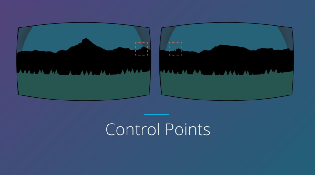
With control points, we can manually edit the stitch line, allowing us to optimize and fix any problems.

Controls points are used to link visible features to occur in both images
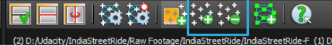
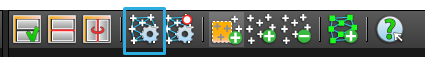
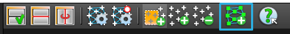
If we select the “Control Points editor” a new window will open.
Click here to launch the control points editor
You’ll now see the Control Points Editor.
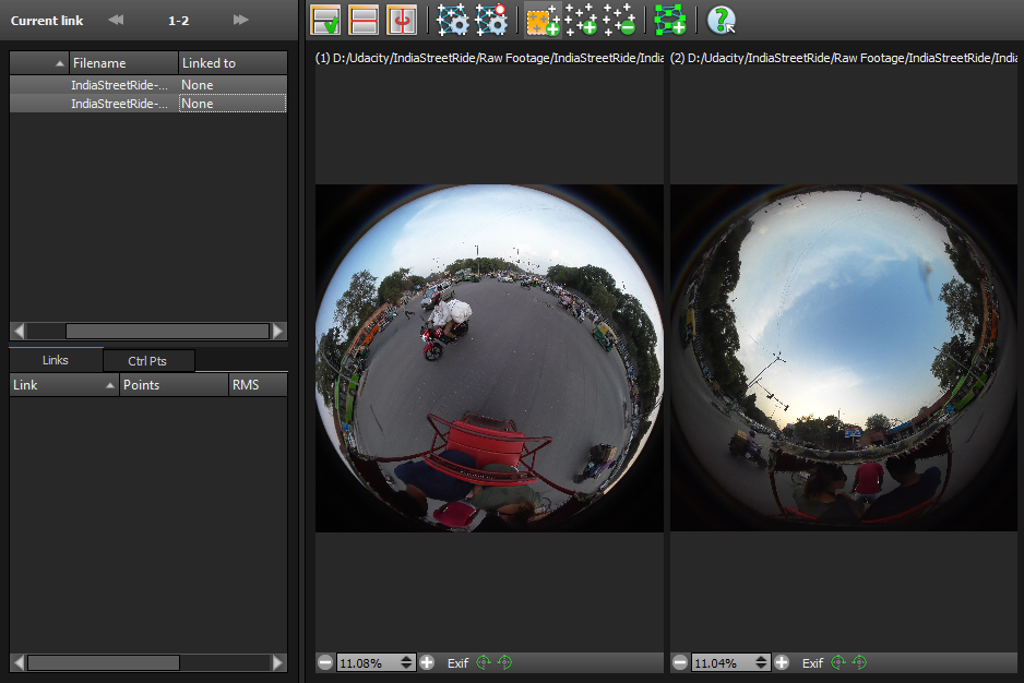
This is the main control points editor
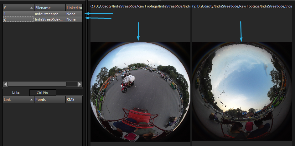
Minimize this window for a moment and go back to the main window - you should now be able to mouse over your image, and see which parts are from which camera. You may notice that there’s some overlap here.
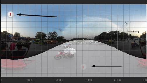
The main Autopano Giga window has changed. Now you can view each camera by hovering over it.
Control points are the way that Autopano Giga processes how two images are linked together - a control point is used to link a visible feature which occurs in both images. By editing these, we can correctly align our stitch.
Allow you to how features are linked between stitched images
Let’s go back to the Control points editor window. By selecting any two images or videos, we can bring them up side by side.
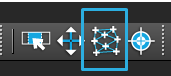
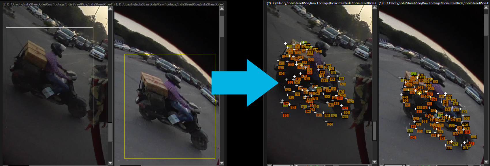
By default, the Auto Add Control Points tool is selected.
The “Auto Add Control Points” tool is selected by default
This tool allows us to select an area on both images that we think has common features. We draw a box on each image around that area, and the program analyzes the image and adds control points.

Workflow:
- Turn off the “Synchronize Views” toggle button so you can independently control each viewport.
- Rotate each image so the the object you want to match is corrected oriented in both images.
- Zoom in on the object you want to match.
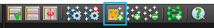
- Draw a box around the object in each image. TIP: You should perform this step multiple times to get more control points around your object.
Draw boxes around each object. Autopano Giga will automatically compute the relevant control points between them.
Each numbered point corresponds to the same number on the opposite side. That means that when the images are stitched, that particular number will be overlaid on the the same number on the other side.
If we want even more control though, we can add and remove control points manually. When you select that tool, the cursor turns into a magnifying glass, allowing us to very carefully select identical features on both image. Click on one image first, and then click the same point on the second - you’ll see the control point labeled with the correct number. You can also remove control points if you make a mistake.
These two tools will let you manually add or move control points.
Once you are happy with the number of control points you have added by either method, then click on the “optimize” button.
Click the Optimize button to restitch the image
Giga will restitch the image, using our control points as a guide. You can repeat this process as often as necessary to get as close to perfect as possible. The quick optimize will optimize only the most recent changes, where the full will optimize the whole image.
When you go back to the main window, you will see the link between the two images now as a colored box, with the number of control points in it. A green flag is ideal - a great stitch.
Fixing Bad Control Points
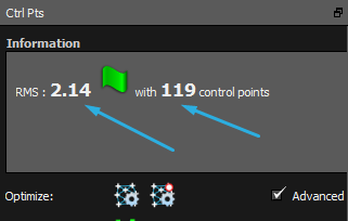
You want a low RMS value with lots of control points.
Generally speaking, you want lots of control points with a low RMS value. If you have a warning sign instead of green flag, then you should fix your control points.
The first step is to go into the Control Points editor, click on the Ctrl Pts tab and sort all of your control points by their RMS value.
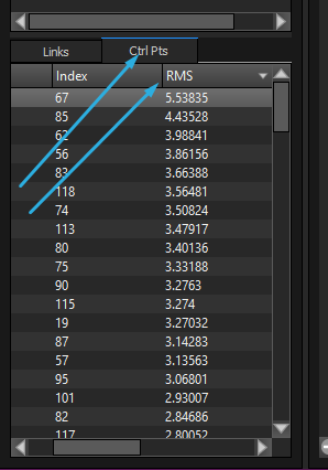
In the Control Points editor, click on the Ctrl Pts tab to sort your points by RMS.
RMS stands for Root Mean Square, and it is a standard measurement of error. In this case, large RMS values mean that the predicted stitch location greatly deviates from the actual sampled location.
Using the Control Points editor, you can remove points with high RMS values by sorting according to RMS, shift-selecting the control points you want to remove, then pressing delete.
If your manual point selection efforts aren’t going very well, then you should also try to use the Geometric Analysis tool inside of the Control Point editor.
The automatic geometric analysis is a great way to generate lots of points automatically.